The basic operation of the physical level of wireless communication
Radio waves, the medium of wireless communication, are called “radio waves” or “Hertzian waves” in English, and are sometimes abbreviated to “radio.
Radio waves are based on Maxwell’s equations, a theory of electromagnetic fields that James Clerk Maxwell predicted in 1864 (the year of the Hamaguri Gomon Incident in Japan) that “light is an electromagnetic wave in the form of a wave,” and his discovery that “light is an electromagnetic wave in the form of a wave” and that “light is an electromagnetic wave in the form of a wave” (Maxwell’s equations, a theory of electromagnetic fields).
\[\begin{cases}\nabla\cdot\mathbf{B}(t,\mathbf{x})=0\\\nabla\times\mathbf{E}(t,\mathbf{x})=-\frac{\partial\mathbf{B}(t,\mathbf{x})}{\partial t}\\\nabla\cdot\mathbf{D}(t,\mathbf{x})=\rho(t,\mathbf{X})\\\nabla\times\mathbf{H}(t,\mathbf{x})=\mathbf{j}(t,\mathbf{x})+\frac{\partial\mathbf{D}(t,\mathbf{x})}{\partial t}\end{cases}\]
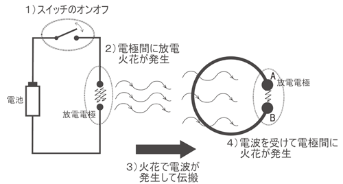
Thirteen years later, in 1887 (the 20th year of Meiji in Japan), Heinrich Hertz deduced the existence of electromagnetic waves (radio waves) with a lower frequency than light from Maxwell’s equations and demonstrated their existence by devising and producing experimental equipment that could generate and detect electromagnetic waves.

Based on those experiments, Hertz also developed the “Hertzian antenna,” which consists of a group of terminals that are not installed, and a dipole antenna for transmitting ultra shortwave (UHF: also called Ultra High Frequency, 300 MHz to 3 GHz, with wavelengths of 10 cn to 1 m). They are the simplest practical antennas from a theoretical point of view.

I will now discuss those antennas that are fundamental to the physical level operation of wireless electronic devices.
First, some common antenna design types are as follows

The most famous antenna is the monopole antenna shown in the upper right corner of the figure. This type of antenna was the most common type of antenna used to receive television signals, and was even used in the first generation of cellular phones and toys.

The Yagi-Uda antenna on the upper left in the figure, which was installed on the roof for TV reception, will also be familiar to many people.

The antenna commonly used in today’s wireless electronic devices is the microstrip antenna shown in the upper right bottom corner. This antenna is chosen because it is the simplest in construction and easiest to manufacture.

An antenna is a type of energy conversion. Electric energy is converted into electromagnetic waves as input and radiated, or radiated electromagnetic waves are captured and converted into electric energy. In other words, a wire basically emits part of the electromagnetic energy transmitted through it, and the reduction of electromagnetic noise on an electric circuit board and the design of an efficient antenna are two sides of the same coin.
However, antenna radiation is a very specific type of radiation (it oscillates only at a specified frequency and has enough power to propagate over a target distance) compared to noise radiation. For example, in the case of Bluetooth, as described in “About IOT (2) Using BLE in Javascript (bluejely),” the antenna has the ability to propagate electromagnetic waves of several GHz and tens of milliwatts over a distance of about 10 meters.
Here is a simpler statement about “energy converters. A transformer takes electrical energy in one form and propagates it in a slightly different form. For example, a transformer changes the ratio of voltage to current in an electrical signal. In other words, a transformer changes the wave impedance of an electrical signal according to the law of ohms. A common example of this transformer is the double-winding transformer used in power grids. (see figure below)

This is done by using a transformer to increase the voltage, decrease the current, and increase the wave impedance in order to transmit the very high-current, low-voltage electrical signals generated at the power plant to a point several hundred kilometers away with minimal loss. This is because the lower the current in a wire, the lower the losses (e.g., heat generation), and therefore, the lower the current, the better the transmission losses.
The function of the antenna will be the same as this transformer in an electrical sense. For example, in the case of the horn antenna shown in the figure above, if we consider a rectangular conduit with a horn antenna attached to the end, as shown in the figure below, we can see how the antenna emits electromagnetic waves from the waveguide into free space.

The horn antenna’s trumpet-shaped aperture basically functions as an energy converter, taking electromagnetic waves of impedance 50 Ω from the coaxial cable through the waveguide and converting them into electromagnetic waves of wave impedance 377 Ω that propagate in free space.
The antenna is the matching element, which is the component that matches the electromagnetic wave propagating through the waveguide to free space. This matching is important because, as in the case of a transformer, the electromagnetic wave that travels through the waveguide must be converted to energy so that it propagates through free space with minimal loss.
In the case of electromagnetic waves, wave impedance is expressed as the ratio of electrical energy to magnetic energy. If the wave impedance of free space is 377 Ω, then for electromagnetic waves to propagate in free space, the wave impedance must be 377 Ω (solving Maxwell’s equations for free space results in a wave impedance of 377 Ω). Instead of solving the equations, this figure can be accurately measured by experimentally measuring the ratio of electrical to magnetic energy in electromagnetic waves in free space.
Let us assume that we are developing a SoC (System on Chip) that detects, processes, and wirelessly transmits water meter data to a gateway; the data stored in the memory of the SoC is represented by a set of zeros and ones, thereby enabling sequential reads, and all data is ready for transmission. The antenna, on the other hand, works as an energy converter. The antenna, on the other hand, acts as an energy converter. The antenna takes electromagnetic energy from the wire, changes its impedance, and sends it out into free space.
In early wireless communications, data was successfully sent directly to the antenna by creating an on/off modulation signal at the antenna end, which was then read by a receiver at another point. To use the example of the SoC mentioned earlier, data (0,1 digital data) is generated at the operating frequency of the CPU, which is several tens of MHz at the current level. Such a huge antenna would not fit inside a small electronic device.
This is because to maximize the efficiency of the antenna, it must resonate at the frequency of the electromagnetic waves to be transmitted (at resonance, the electromagnetic energy continues to oscillate between the ends of the antenna, so that the energy is not reflected back to the signal source and is maximally retained in the antenna), and to resonate the antenna In order for the antenna to resonate, the dimensions of the antenna must be equal to half the wavelength of the propagating electromagnetic wave. In addition, there is a relationship between the frequency and wavelength of the propagating wave and the “speed of light = wavelength x frequency,” and using this relationship, the antenna dimensions for a signal of several tens of MHz would be about 15 meters. (3.0×108 = wavelength x 20×106)
In order to miniaturize the antenna, it is necessary to make the signal high-frequency, which requires modulating the CPU operating speed (low-frequency signal) using a high-frequency carrier (carrier wave) such as amplitude modulation (AM) or frequency modulation (FM) (see figure below). (see figure below).

In the case of Bluetooth, the carrier frequency is 2.4 GHz, which allows the antenna dimensions to be reduced to 2xm.
Furthermore, by dividing this carrier frequency into small bandwidths called channels, two nodes in Bluetooth communication can share the channel used for communication as follows, allowing different nodes to coexist and communicate simultaneously.

In the next article, we will discuss RFID technology.

コメント